What the point of 3-state buffer? It intended to use as gate for bus? When the buffer is Enabled, bus pass though it to more common bus? What the difference between the 3-state buffer and the AND? thank you.
44 days ago (+1)
TL;DR: A 3-state buffer acts like an electrical switch (connected/disconnected), while an AND gate is always actively sending a signal (1 or 0). If you connect multiple AND gate outputs to a single shared bus, they will fight each other (it’s called a short circuit). 3-state buffers prevent this by completely disconnecting components from the bus when they aren’t in use.
In details: To understand why we need 3-state buffers, you have to look at how a Shared Bus works in a CPU. A bus is just a bundle of shared wires. Many different registers (like Program Counter, Register A, Register B) need to write their data to these exact same wires depending on the current instruction.
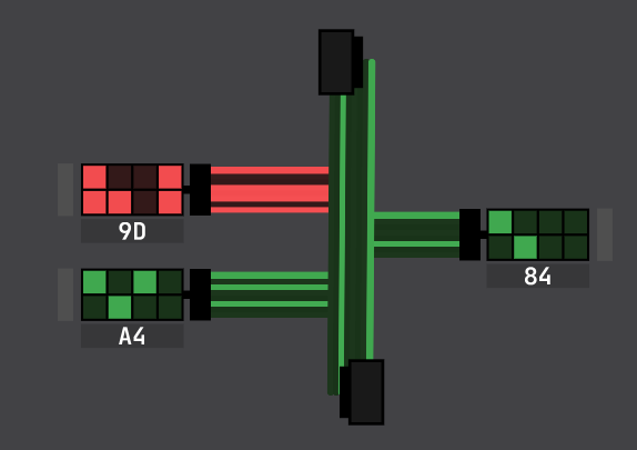
Standard logic gates always output something. They are either actively pushing voltage (1) or actively pulling it to ground (0). If you connect the outputs of two AND gates directly to the same bus wire, and Gate A tries to send a 1 while Gate B tries to send a 0, you create a direct path from power to ground. This is called bus contention (simply a short circuit). The data becomes corrupted, and in real hardware, the chips would overheat and burn out.
A tri-state buffer solves this by adding a third option. Its states are:
- High (1)
- Low (0)
- High-Z (High Impedance / Disconnected)
When the buffer’s Enable pin is OFF, it enters the High-Z state. It acts as if the wire was physically cut. It doesn’t output a 0; it outputs nothing.
Want to see some fireworks in DLS? Build a circuit just like the one in the attached picture and see what happens. The exact same thing—only much worse and with a release of “magic smoke”—happens in actual silicon when you forget about 3-state buffers ;)